Huh, I just checked the waveform with the switch in On/Off mode, relay enabled and clicking, and to my surprise, it looks like it does when in dimmer mode at 100% brightness–it’s actually still using the dimming circuitry and not sending out a pure sine wave ![]() From what I understood from the previously-linked thread, this is not behaving as expected: “We were able to add the relay function … so that there’s more of a, “hard on/off” for single-pole settings.” “… we haven’t had any complaints around flickering or safety concerns in on/off mode, at least there will be an override if someone experiences this.”
From what I understood from the previously-linked thread, this is not behaving as expected: “We were able to add the relay function … so that there’s more of a, “hard on/off” for single-pole settings.” “… we haven’t had any complaints around flickering or safety concerns in on/off mode, at least there will be an override if someone experiences this.”
Slightly concerned on this. If the dimmer module cannot be bypassed and it cannot put out 100% sine wave power, will it damage non-dimmable lights?
I’m not personally affected by this – i think my lights are dimmable. But when i see “on/off switch” my assumption would be it outputs unmodified sine wave power
It’s exactly what I expected. The relay is a form C contact switching the MOSFETs between the traveler and load screws. It doesn’t bypass the MOSFETs.
Popping in here to say I’ve noted this thread and am bringing it to the engineers to give an explanation. If this was a, “head-fake” last minute to simply add an audible click, there’s going to be an issue for sure.
Thanks for running these tests @dahanc!
Did they promise trailing-edge dimming, or was the decision made to go with leading edge bc it allows non-neutral setups? The reason I ask is that the one Blue I’ve installed so far replaced a Zooz Zen27, which uses trailing edge. The Feit LED bulbs on that circuit dimmed nicely with the Zen27, but with the Blue the bulbs put out a buzzing noise when not at full brightness. I’d keep the Zen27, except it just wasn’t fast enough wrt automation execution in that location. Zigbee has improved that situation, at least…
Here are my raw notes/conversation from when this was brought up with the PM from the manufacturer. I’m not an engineer by any means so rather than trying to interpret this for you guys, I’ll just share what I have.
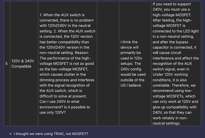
We initially asked for TRIAC bc it seemed like MOSFET was not as compatible with bulbs (Zooz being the brand often referenced when bulbs wouldn’t work with our switch). Initially it seemed like this was ok (as referenced my my quote where they said TRIAC can both be used with dumb & aux), but I think they realized later that it was not possible.
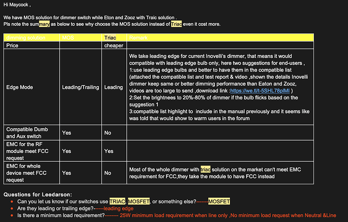
Here is the original notes from our Red Series manufacturer as to why MOSFET (Leading Edge) was chosen (sorry for the highlights, I was searching MS Outlook for the email and those were the keywords).
Based on the above picture/chart, it’s saying that TRIAC is not compatible with both Dumb and Aux switch, nor will it meet the requirement for EMC (I disagree bc there are examples in the market – for the record so did our current manufacturer, but the bigger point is that TRIAC will not work with both dumb/aux).
–
I think this is the same conclusion our current manufacturer came to as shown in the first few pictures.
The question outstanding though is why leading vs trailing. I honestly don’t know the answer to that and I’m happy to ask once things calm down a bit with the engineers.
The weird thing is that most information I’ve found online says that MOSFET uses trailing edge – is this true?
Triac can only do leading edge, since it uses the next waveform zero crossing as an auto-shutoff signal (that’s my understanding). MOSFETs can do whatever you want, I think…
Edit: does anyone know if a MOSFET trailing edge requires a neutral? Maybe this is why Inovelli ended up with a leading-edge configuration… I would happily forgo the non-neutral option to get trailing edge dimming. Looks like hardware changes are required to swap between the two, though, so with the current switches we’re stuck with leading-edge. Guess I’ll have to do some research on replacement LEDs that will work with this type of dimmer. Disappointing, but I understand not wanting to break out a separate SKU for non-neutral folks.
Lutron has an app note, “Challenges of Dimming LED Loads on ELV and MLV Transformers” which is pretty informative. They don’t state that trailing-edge requires a neutral, but do note:
Most ELV dimmers require a neutral wire for proper operation which helps the dimmer switch on and off properly, regardless of load characteristics.
That same app note claims that forward/reverse in the same dimmer is possible:
There are also “universal” or “adaptive” dimmers, that are capable of creating both forward-phase and reverse-phase waveforms, either through manual configuration or by automatically detecting whether the load is inductive or capacitive. Universal dimmers can be extremely useful, as they can be selected without prior knowledge of the type of transformer that will ultimately be installed.
I’d be curious to know if any devices in the market are actually universal, but it sounds like it’s possible.
Interesting that the Lutron C•L version of the Diva dimmer (model DVWCL-153P) is leading-edge, and doesn’t require a neutral. The trailing-edge version (DVRP-253P) does require a neutral, and is significantly more expensive, so perhaps the hardware differences are significant.
I thought I had the trailing version of the Diva, but it’s the -153P, so is leading-edge. Despite this, the LED compatibility is fantastic, so leaves me feeling a bit better about how good forward-phase can potentially be.
We are seriously considering this. The main driver being B2B sales as they are much more price conscious as we’re competing against the Jasco’s of the world who can offer a much cheaper switch and B2B generally doesn’t care about all the bells and whistles.
If it happens, add my vote for a higher-end consumer version that’s neutral-only and does reverse-phase dimming, please!
I have a few Leviton DZ6HD dimmers, which Leviton claims to be universal. What exactly they mean by that, I’m not sure, but there is a setting for load type with incandescent, LED, and CFL as the options.
Unfortunately, I don’t have an oscilloscope to check to see what it’s doing.
Following on the on/off mode waveform topic, I have a question: is the MOSFET module capable of output 100% on, unmodified sine-wave power, after some firmware change? Maybe someone with experience in EE field can answer this…
The problem is, currently in on/off mode, the output power is only on for 88% of the time, as @dahanc has observed. (I think) the desired behavior is power-on should be 100% of the time.
I don’t know the answer because I don’t major in EE. But @epow said “MOSFETs can do whatever you want, I think…” and i also heard MOSFET is very versatile. So maybe this is possible?
edit: Blue Series Dimming Tech - #27 by epow - General Discussion - Inovelli Community just saw epow’s comment. So perhaps it’s impossible without hardware change (?)
I’m curious, if the output power is on for 88% of the time, would that mean that the light is ~88% of full brightness?
I’m curious, if the output power is on for 88% of the time, would that mean that the light is ~88% of full brightness? @Glenn
I’m not an EE engineer so I cannot give an accurate answer. my guess is there won’t be a noticeable difference. Because (1) It’s on 96% of the sine wave area, and (2) human’s perception to brightness is logarithmic, not linear [^1], so 90% and 100% probably is not that different.
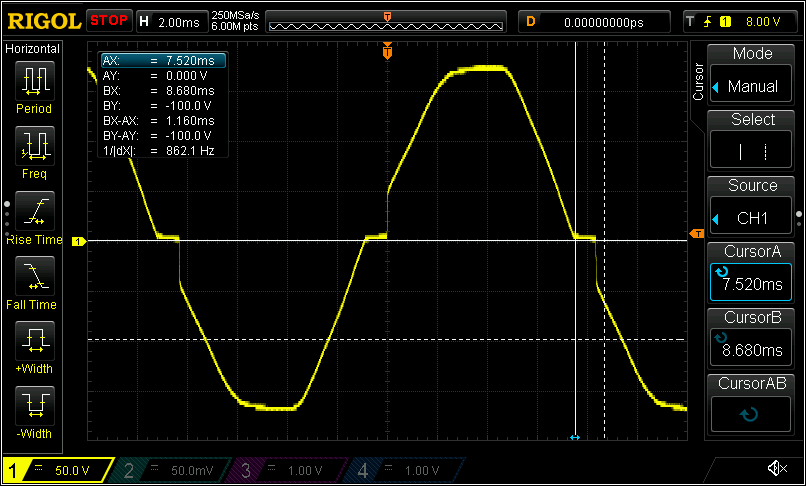
Brightness 100/100, power on for about 7.360 ms out of 8.333 ms, or 88% of the time, 96% of the sine wave’s area
I have no knowledge about the dimmable LED driver design though.
Someone pls correct me if i’m wrong. ![]()
[^1] Based on my (very limited) knowledge in computer graphics.
I heard that most of the dimmers cannot output 100% power. My concern is less about brightness but more about “will it damage non-dimmable lights in long term?”
But again, if it’s possible to get higher brightness with just a firmware update – then I will definitely be happy about it.
The PRO versions of the maestro non smart switch (model MA-PRO) supports both leading and trailing (aka forward and rsverse) edge. You can adjust it in the settings. They work great on lots of different LED types and are worth the upgrade from the cheaper 153 series. Of course, they’re also non smart.
https://www.lutron.com/TechnicalDocumentLibrary/3691112_ENG.pdf
More details:
Can someone TLDR this for me? I’m trying to talk to the engineer about this and it’s way above my head.
What I’m looking for specifically is:
- What is the problem? Why is this a problem?
- What is the desired outcome?
Bonus points if you can dumb it down for me (marketing major) so I can understand it as it makes it easier for me to explain the issue to the engineer.
–
I asked him about the, “click” and what that entailed and this was his response:
"Hard click"completely shuts down the load, and the relay disconnects the circuit without leaking weak current.
He also noted that the hard click requires the neutral wire.
The problem is that when the switch is configured as an on/off switch, when it’s on, it’s not passing the full sine wave to the load. It has a step, as shown in the image below.
This is a problem because some loads can’t handle that sudden voltage step seen at the center of the image, where it’s basically a flat horizontal line then there’s a vertical jump up to that faint gray grid line. For example, I’m pretty sure that’s what’s causing the transformer buzzing reported in this thread
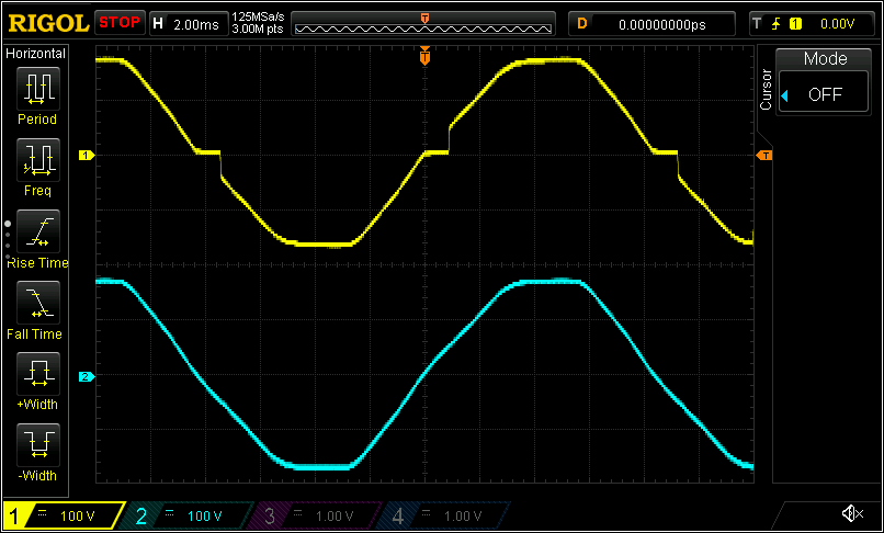
And the desired outcome is for the switch in on/off mode to pass a smooth sine wave to the load, like the blue trace in the bottom image. If possible, the relay should click to connect the line directly to the load without the dimming circuitry being involved. But if the dimming circuitry is always going to be active, perhaps the MOSFETs could be turned on for more of the time to reduce/eliminate the step.
Switch configured for on/off, relay click is enabled:
This is perfect, thank you!
I edited my previous post to show the switch in on/off mode. Hope this helps!
I would also add that since solid-state technology (MOSFET transistors) are being used to perform the dimming, it really should be set up to do trailing-edge dimming. Maybe a bit more $ for parts (feel free to pass it on to the consumers), but well worth it as it will vastly reduce the number of incompatible LEDs. It’s a head-scratcher why your engineers chose to use MOSFETs for forward-phase dimming… TRIACs would have been cheaper.
