Good point and I agree 
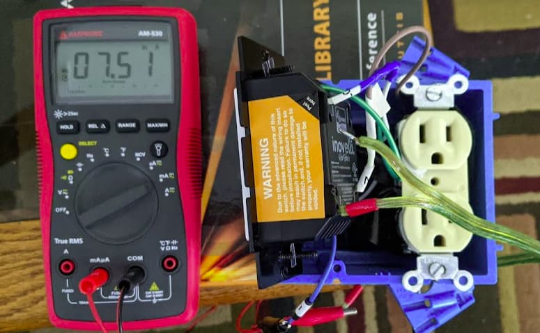
For comparison, I hooked a Red switch in my bench jig. Using a multimeter, I measured the current of line in to the switch, with no external load. This is an “industrial” meter, not a calibrated lab device, however should me more accurate than a Kill-A-Watt type device.
For a check, I put a 100Ω resistor between line and switch. There is obvious discrepancy between the two methods, but they are within the ballpark of each other.

The problem with measuring current on an AC system and then assuming that the wattage is current times voltage is that you don’t know the power factor.
I would guess that a dimmer is mostly resistive. Maybe not purely resistive due to the relay. If it’s purely resistive, the PF is 1, so it would be no factor.
Even if there is a power factor, it’s going to be so small that it’s probably going to be statistically insignificant. And if the PF troubles you that much, calculate at 0.8 PF and consider the resulting value to be a range between that and a calculation with no PF. Or just consider the calculation without a PF to be the max . . .
No-one responding knows what the power factor is. I’ve worked with AC for too many years to ignore it or guess at it. The power supply for the internals could use a capacitor to drop a bunch of the line voltage, which would give it a very poor power factor.
I’m going to try to measure it with a scope with power measuring capabilities, just not sure when.
Let me check with the manufacturer. Hopefully they can shed some light (pun intended) on it.
Well, the current is an odd asymmetric waveform making it impossible to get the power measurement right using a meter. I’d say a quality scope or similar is the only way to measure this.
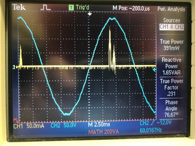
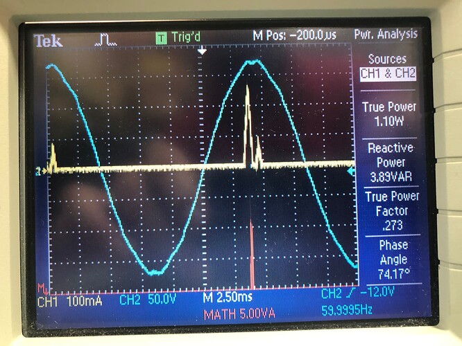
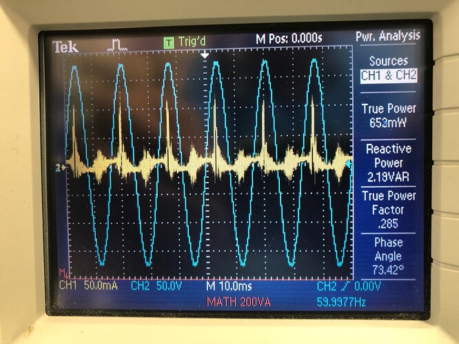
This is measuring a black switch with no load connected.
Off
On
About 0.4W when off and 1.1W when on.
I was measuring the current through a 5% tolerance 1 ohm resistor by setting the scope to the 1A/V scale. So, the current signal is quite low and that makes it kind of noisy, but it’s good enough to give a reasonable idea of what the power draw of this switch is.
I want to test a red switch and also test with a load connected next and see how much current it leaks since that’s been another complaint about the switches.
I tried to measure the load leakage current on the black switch a few different ways. I was always getting less than 200uA. The best way I tried was connecting a 100ohm resistor as the load and measuring across it with the scope set to 1A/V. The scope was reading was 16mA RMS and this reading is 100X the actual current making it really 160uA. It seems the switch really doesn’t leak much current and it doesn’t explain why led loads will glow when connected to one.
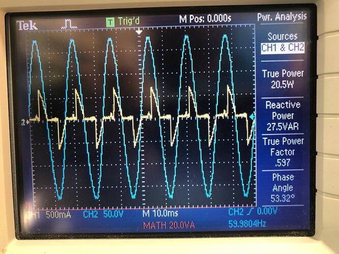
Next I connected a RED dimmer. These are the power measurements.
On or Off with no load connected.
Off with a 40W incandescent bulb connected.
The above shows the dimmer leaks a lot more current to the load. Likely due to the ability to operate without a neutral.
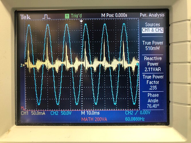
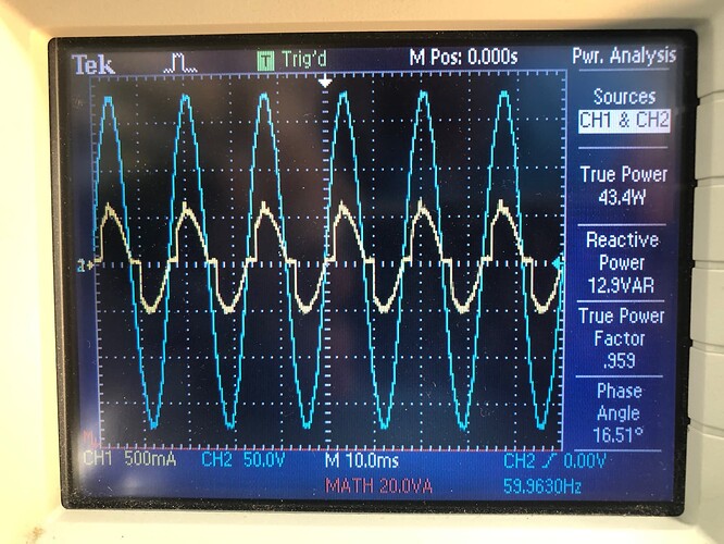
And just for fun, on at about 1/2 dimmed with that 40W bulb.
The conclusion from this last one is that it’s definitely a leading edge dimmer. Previous info has said this is MOSFET based which is needed for trailing edge dimming but IMO it is pointless to add the complexity of using MOSFETs for leading edge. I’m curious why it’s not a trailing edge dimmer because that seems to make LED loads more happy.
And a last one, dimmed fully on.
Which shows the dimmer never truly goes fully on. There is actually more off-time then I expected to see.
Awesome posts @PJF!
A couple of thoughts. First, @Eric_Inovelli @EricM_Inovelli - If current draw of this switch really is ~0.5W, pending manufacture confirmation, of course, then I think we should open a bug or enhancement ticket to get the switches reporting the correct usage on the net energy consumed readings. Right now the switch reports about 2.5W consumed every 24-36 hours. With new energy monitoring coming to hubs and LEDs only drawing 6-8W, these switches are going to start showing up as energy drains and this conversation will continue.
This is what I saw on my scope also. Leading-edge and never full power delivered. I think we are all chomping at the bit to get the source code because this appears to be lazy programming for the hardware available.
Great work PJF!
Yes, the switch using a off state draw of around 2.5W when calculating the kWh energy data doesn’t appear right and it will mess with anyone wanting to actually track their energy usage. The switch shouldn’t just be programmed to use 0W in the kWh calculation though, because it’s not really 0W when off.
@PJF As someone that doesn’t have the equipment, can’t justify the cost, but loves seeing this level of detail and has just enough academic knowledge to understand the graphs produced by it: Thank you very much for the scope pictures and the analysis of some of the finer points around A/C devices. This is very much appreciated!
@PJF I wonder if the fix for that is just a firmware update. 2.5W seems to be constantly reported and as accurate measurements of <1W are tricky to implement on the switch it should be a software fix.
@All
Is there a good way to reach the developers? Does Inovelli have a ticketing system?
Yes, most likely they’d have to change the software and report a fixed off value. The off-state power consumption will change depending on the relay being on or off which can happen in a dumb 3-way configuration.
I believe the best path to reach the developers is @EricM_Inovelli and yes they do have a ticketing system. You can submit a ticket here: Knowledge Base Redirect – Inovelli
The specs for the MCU (Z-Wave) & Holtek, LEDs, etc. on the switch and dimmer should draw about .5w - 1w when the load is off (closer to .5 from my experience). I have requested that the manufacturer look into improving the accuracy of the KwH reporting.
Edit: Oh, and the devices report 0w usage when off as to not confuse the user. We did have a firmware version that came out where 1w was reported (rounded up), but I think I remember a lot of people being confused. Another option is to not report the power usage of the internals in the KwH report. That might be easier for the engineers to implement.
Thanks @EricM_Inovelli , good information.
I would prefer that KwH keeps the current draw from the switch included but instead uses the 0.5w draw instead of the observed 2.5W draw it seems to be using right now. I like that that value is ‘honest’ about the overall power usage of that circuit.
As always, we appreciate the willingness to adapt and improve!
The devices say 0W, but the kWh calculation seems to be using 2-2.5W in the calculation while off.
It would be best to include switch power to be completely truthful about the numbers, but it’d be better to not report it in both the kW and kWh than what is currently done.
@EricM_Inovelli @Eric_Inovelli - Any word from the manufacture if this can be adjusted in a future firmware release? The WAF is dropping as she thinks the power from all my smart switches is what’s driving our high electricity bills and I think it’s because she leaves the lights on. 
The switch consumption isn’t going to change just because the firmware changes how it calculates. The draw is between .5 and 1 W so you can do the math from that . . .
