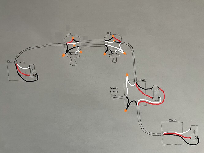
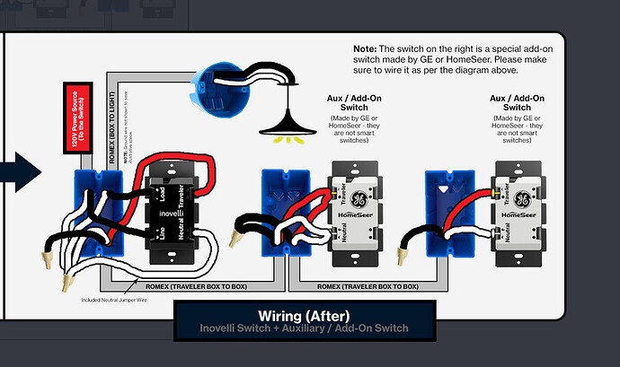
This is my mess of a circuit. Will a LZW31-SN and two aux switches work here?
Potentially yes, but could you label wire colors? I’m having a hard time tracing between the boxes.
I updated the image, hope that helps. The “thinner” black line is the white wire. Apologies for choosing green as the wire nut color 
Waiting to see what @harjms comes up with.
In the interim I’m gonna say you could do something with SW2 and SW3 but you’d have to exclude SW1. The Achilles heel is that there is only a 2-wire between the two lights. So you only have room to send a switched hot and a neutral past the first light, with no conductor for signaling.
If necessary, it actually wouldn’t be too difficult to replace the 2-wire between the lights with a 3-wire.
Let’s see what @harjms comes up with as-is, but here is the theory if you have a 3-wire between the lights.
The Inovelli goes in SW2. You have a neutral there, so it’s a neutral installation. SW2 and the two lights are then wired as a simple 2-way Line/Load same box configuration. You send the Load (switched hot) and neutral to the lights over the black and white of the 3-wire. You re-wire at the lights and the “other” which I’m presuming are more lights to put all lights in parallel.
So now you just have to implement the Aux switches at the remaining positions. In a neutral configuration, an Aux just needs a neutral and a signaling wire.
So for SW3, you send the neutral from SW2 over the white and the Traveler over the red. The black in the 3-wire between SW2 and SW3 isn’t used.
For SW1, you have to get a neutral and a traveler (signaling conductor) over to it. Starting at SW2, send the traveler over the red of the 3-wire to LT2, where it’s connected to the red of newly added 3-wire to LT1. At LT1, send the traveler over the red to SW1 and the neutral over the white. The black of the 3-wire between LT1 and SW1 isn’t used.
It’s really this with the devices rearranged:
Oooof…I always rely on you.
The first problem I see is the WHT from the source is going to the COM on SW 3…I honestly am not following the path. Is BLK Line or WHT line?
If there is a problem with SW1 because of two wire, we could always recommend a dimmer without a load and use association…
Edit: Let me get through my coffee and relook at this cause I’m still draggin…
I tried following the path too and gave up. It made my head hurt. There is some sort of voodoo hybrid switched neutral thing going on here. Easier just to focus on how to implement the new stuff.
I though of that, but with only a 2-wre between LT1 and LT2, you can only send a SWITCHED hot so no way to power SW1 full time.
I’m glad I wasn’t the only one confused.
I’ve had this whole circuit opened up so many times to double-check everything because when I diagrammed it, it didn’t make sense.
I’ll take another look at things again today. BLK is line from the source.
Yep. It’s not uncommon to drop the line in the middle box with the 4-way switch, but usually there is a 2-wire run to the lights from that box and then a 3-wire(s) out to the switches. But that’s not what you have.
Ugh. I think I screwed up when I edited the diagram and highlighted the black wires. Going back over it again…
Ok, post back when you think it’s good.
Third time’s a charm, I hope. This diagram makes a LOT more sense.
Lol, I guess I got you thinking when I referenced the “other” lights.
This makes much more sense. Way easier with two 2-wires between the two lights.
Pretty much the same as before.
-
Inovelli at SW2, wired initially as a 2-way Line/Load same box.
-
From SW2 to LT2, send neutral over white, load over black and traveler over red
-
At LT2, black switched load to one light terminal and the white neutral to the other. Bridge in parallel via one 2-wire Romex from the light to LT1.
-
At LT2, connect the red traveler from the 3-wire from SW2 to the white of the OTHER 2-wire going to LT1. Cap off the other black conductor.
-
At LT1, connect the black and white from the proper 2-wire Romex from LT2 to the light. Connect the white from the other 2-wire Romex from LT2 (which is the traveler) to the red on the 3-wire going to SW1. Connect the white neutral connected also to the light to the white on the 3-wire going to SW1. Cap off the black on the 3-wire going to SW1.
-
At SW1, white to the Neutral terminal, red to the traveler
-
Back to SW2. 3-wire going to SW3, red to traveler on the Inovelli, white on the neutral on the Inovelli.
-
At SW3, white to the Neutral terminal, red to the traveler
I think that’s it. Make sense?
Awesome, thanks! Will give it a shot this evening!
Everything is working. I’ve been trying to figure out how to get a smart switch on this circuit for years. You guys rock!
Great to hear! Make sure you mark the correct post as solution so we know it is resolved!!!
Glad to help. Your updated drawing certainly made it easier, LOL.

