I’ve linked 3 pictures above with the current setup. My electrician installed the red series dimmer when we built the house and two additional dumb paddle switches in the middle and other end of the same hallway. I’d like to replace the two dumb switches with white series aux switches. I tried to color code pairs from the same wire in the pictures. Any help with how to convert the dumb switches is greatly appreciated.
In box 3, there is a black conductor with a pink dot that is attached to the black screw of the dumb switch. Does that black conductor belong to a 2-wires Romex? i.e. Black and white conductors with a bare ground.
The white is probably connected to the white coming from box 2 or a neutral bundle.
I think this is the load box but need to confirm.
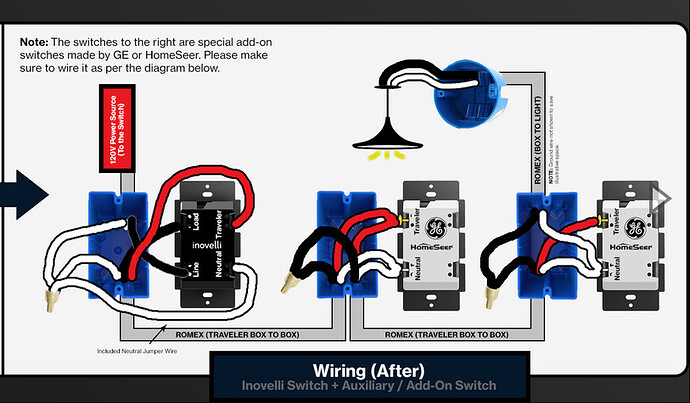
Thanks. It’s a little tough to see into the box without everything pulled out. But if the black conductor on the black screw is connected to a 2-wire, then that appears to be your load. So based on the fact the Inovelli is in box 1 and the load appears to be in box 3, you have a line and load in separate boxes. If that is the case, and it is up to you to confirm as I can only see so much from pictures, you’ll use the following wire diagram:
What you are doing in essence is the following:
1 - Using the red and white of the 3-wire between the boxes, you are sending the traveler from the Inovelli and neutral to boxes 2 and 3, where they are connected to the terminals on the Auxs.
2 - Using the black from the 3-wire between the toxes, you are sending the load from the Inovelli to box 3, where it is connected to the black load conductor from the 2-wire. It is passed through box 2 by connecting the two blacks with a wire nut.
Thank you @Bry ! I’ll try to get a better picture of box 3 for posterity and anyone who runs across this thread on the future. Thanks so much!
As promised, here is a slightly better picture of the main wire the black screw is connected to. It looks like just the black wire, copper, and a neutral white?
If you are asking me if I can tell from that pic, I can’t. With the power off, physically touch the black conductor and follow it back to the sheath. Then observe other conductors coming from it. Sorry, but I can’t tell from that pic.
@Bry ,
I did my best this go around, following your directions from the last pic. This is the best picture I can get with the power off and pulling the wire as far out as possible. My finger is on the main wire in the back. There is a black wire (going to the black screw), white which goes to a wire nut of other neutral tied together and an exposed copper ground.
Sorry for the back and forth on this one. I’m just trying to get this right and it’s a five switch box which makes this tight with wires. Thanks!
Ok, so that is a 2-wire as I expected. It SHOULD be going to the load.
Since your electrician installed the Inovelli previously, it seems likely that the Line is in the box with the Inovelli. But to be doubly sure that 2-wire your finger is on, kill the power and remove the black conductor from the dumb switch in the box you have your finger in. Then power up and using a meter, test between that black conductor and the bundled white to ensure there is no power.
If that black is not hot when it’s disconnected, it’s the load. If that is the case, then the diagram I posted previously is correct.
Just for clarification before pulling it back out.
- Kill power
- Remove black wire from dumb switch
- Restore power
- Multimeter on the exposed hanging black wire and the white wire coming out of the same wire that my finger is on.
- Ensure no power reading
You could also double check the terminal on the dumb switch that you removed the black wire does have 120vac present too. It should not be on the BLK wire, but should be present on the terminal screw that the BLK wire connects.
