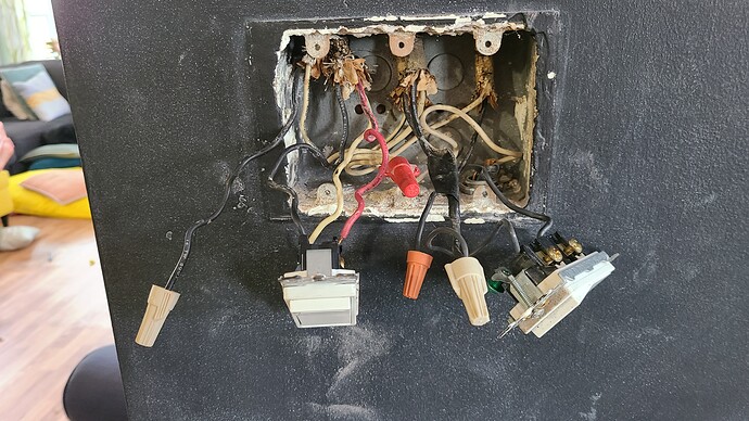
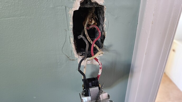
I would like to replace one of the switches in this setup with a smart dimmer (e.g., red series dimmer), but I have a 3-way setup that isn’t covered by the Inovelli diagrams. The switch on the left in the picture with two switches and the single switch in the other picture control the 4 recessed lights that I would like to use the smart dimmer for. The switch on the right in the picture with two switches controls an outlet. Both of the current 3-way switches are wired from a single bundle in their respective boxes. Is it possible to use a smart dimmer in this setup?
Was the black capped wire on the left connected to anything?
You cannot use a dimmer for the switched outlet.
You can use a dimmer for the switch on the left controlling the four cans.
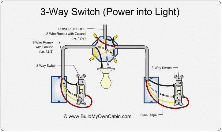
Here is what you have. At each of your switches, you only have one 3-wire. This suggests to me that the constant hot is first coming into your light(s). If you look at the diagram, you will see that a constant hot is routed to one of the boxes. But there is no neutral in either of the boxes.
The first step is to determine which of your two switch boxes gets the hot first. Remove the conductor from the black (common) screw and USING A METER, test between that conductor and the ground. I hope your metal box is grounded.
Once you figure that out, you should be able to put an Inovelli dimmer in the box with the hot and use an Aux in the other box. It will be a non-neutral installation.
If you can get at it and you’re willing to do rewiring at the can box that first gets the power, then we might be able to do a neutral installation and dictate which box the Inovelli goes in. No promises there, though.
And yeah, what is that 2-wire with the loose capped black conductor, if you know?
Thanks for the replies.
I don’t know what the two capped black wires are; they were like that when I opened the box. There is also another black wire that’s taped to the black wire going into the white nut that goes to the outlet switch on the right. I don’t know what that’s about either.
I don’t have a meter, but I do have a voltage tester; would I be able use that to determine which switch gets the hot first? If not, I’ll have to order a meter.
It’s hard to see, but in the first picture that there is a bare copper wire coming in at the bottom right.
By “Aux”, do you mean an add-on switch like this? Amazon.com
It wouldn’t matter that much to me which box had the Inovelli switch, so I wouldn’t care to rewire the can box.
You can try a non-contact voltage tester if you like. It should work. I’m not a big fan of them as some of them sense too broadly. But if that’s what you have, it’s worth a shot. Just pull the conductor far away from everything else to minimize the chance of sensing stray voltage. If you get a hit on one and not the other, you’re probably correct, but with a meter you would know for sure.
Yes, the Aux you linked is one of the supported models.
I’ll give that a shot once I have an Aux switch. Thanks for the information.
Actually, I still have a couple of questions:
- The wiring diagram in the non-neutral 3-way instructions (Knowledge Base Redirect – Inovelli) shows four wires going into the Inovelli dimmer. Given that I only have three wires, how do I wire the dimmer? Am I wiring the hot into the dimmer “line”, the red wire into the dimmer “traveler” and the other wire into the dimmer “load”?
- The aux switches referenced in those instructions all seem to say that a neutral is required.
a. I just want to confirm that I can use one of those in my setup that doesn’t have a neutral available in either box.
b. If so, I wanted to ask how to determine which wire goes into the aux “neutral”?
c. The third wire in the aux box (i.e., the one that’s not the traveler and not the one wired into the “neutral” location on the switch) gets capped, correct?
Thanks again.
This is a bit complicated, but here is how this works. This is based on your wiring being as it’s commonly wired in the drawing I posted above and what I’ll post here. This is how it’s typically done, but it’s ultimately up to you to confirm.
You are going to have a non-neutral configuration in the box that has the load going to the light (I misspoke before). When you have a non-neutral installation with an Aux switch, the Aux actually needs a hot, not a neutral. I know it doesn’t make sense, but the hot goes into the neutral terminal on the Aux.
So right now, more than likely, you have this:
The Inovelli goes in the left box, where the load to the light is. So for a non-neutral installation, the Inovelli just needs a hot and a traveler. The red and the white should be pass-throughs at your light box, so you can use that black to send the hot from the right box and the red as the traveler.
That’s the short version. I can draw this out for you so you can take a look to get a better understanding. @harjms can take a look to confirm.
Looks good to me.
The AUX switch does state neutral, but people have been using LINE instead of neutral (basically still AC) and of course the traveler.
So, to make sure I understand this @Bry, assuming that my setup looks like what’s in your diagram:
- Aux switch goes into the box that gets the hot first
- Aux switch is wired with black (hot) to one of the “neutral” labeled holes, white to the other “neutral” hole, and red to “traveler”
- Inovelli dimmer goes into the other box
- Inovelli dimmer is wired with white to “line”, black to “load”, and red to “traveler”
Is that correct?
Inovelli will go in the box with the hot first. Then you use one of the conductors from Box 1 to Box 2 to send LINE (WHT or RED) to the AUX switch.
Yep, that’s it! If you want you can do it in stages. Wire it as a two-way first by not connecting the red traveler. That way you have a simple non-neutral two-way. Set parameter 21 to non-neutral and parameter 22 two single pole.
Once that works, add the traveler for the three-way. Change parameter 22 to multi switch auxiliary switch sometimes labeled three-way momentary.
@harjms connections look correct?
That’s what I first thought but I don’t think you can do that, because the load is in the other box. You need the remaining two conductors to send hot and traveler to the other box, so nothing left to bridge the load.
@Bry - ahh crap I forgot about the load being in a different box. Basically there’s a few ways to do it, but the way @Bry describes doesn’t require any re-wiring in the light.
@yankfade - ^ Bry’s wiring is correct. Belay my last on Inovelli in the Hot box.
No problem. Bear in mind that since you are using a non-neutral config, you might need a bypass, depending on your load.
Right, though the load is 44W, so according to the instructions that should be enough to not need a bypass.
True, although experience shows that not a hard metric. Depends on the bulbs. Let’s see what happens.
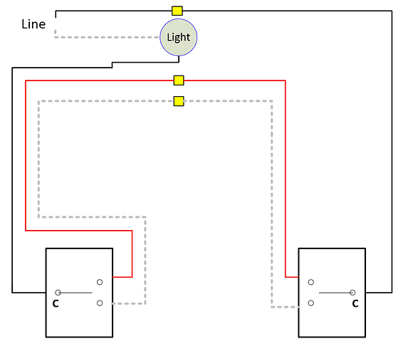
Based on the drawing, I don’t see that it matters which box is used. The current flow through the switches to the load is the same either way.
For me the unknown is how reliable will the Inovelli ‘non-neutral’ 3-way sense logic work with its 'hot" terminal (‘C’ in the drawing) going to the load (if installed in left box) instead of true ‘hot’ (if installed in the right box)
It may work either way, but my gut feeling is putting the Inovelli in the right box would be closer to the Inovelli examples with Line/Load in different boxes (and possibly more reliable with a constant true hot going to the Line terminal on the Inovelli)
Based on the drawing, I don’t see that it matters which box is used.
So if you put the Inovelli in the box that first gets the power, how do you propose to get the load to the other box (where it goes to the light)? You have three conductors in that box. One is bringing in the constant hot. The second is the traveler to signal the Aux. The third is being used to send the hot to the Aux. You’re out of conductors!


